Power Dissipation is the major specification any component. The thermal performance of the diode can be judged based on the power dissipation characteristic of the diode. Diodes are available with different characteristics can be used for different applications like regulation, reverse protection, surge protection, Rectification, Isolation, generating light like the LED. Whatever may be the application, understanding the datasheet and the circuit requirements are critical for proper functionality at a localized circuit level and hence the complete product level.
Let us focus on how the power dissipation specification of a diode plays an important role. We are considering RB578VYM100FH from ROHM for our analysis. RB578VYM100FH is a schottky diode used generally for reverse voltage protection in circuits.
Point#1 - Consider the graph
The power dissipation is multiplication of voltage and current. Generally, diodes provide a Forward Voltage vs Forward Current graph which helps us to decide upon the maximum current and usability of the diode because of the forward drop. Every diode datasheet shall have VF-IF characteristics similar to the one below in RB578VYM100FH datasheet.
The above graph indicates the relation between forward voltage, forward current and Temperature. The point here is that as the current through diode increases the forward drop also increases. For reverse protection, if the diode is used in series with the main voltage at the input, below two inputs need to be considered:
- How much forward voltage has dropped across the diode
- What is the maximum current that can be passed so that power dissipation doesn't increase beyond a certain limit. If the power drop increases, either the designer has to provide heat sink to pull the heat from the diode or restrict the diode till the maximum allowable power dissipation it can be used
Point#2 - Calculating the power and checking thermal
At any given current, consider the forward drop and multiply both to get the power dissipation. Consider the below specifications, from the datasheet.
From the above specification, Power dissipation = 0.85*0.7 = 0.595W.
We can consider from graph to see the respective current, voltage and temperature and calculate power dissipation.
Some of the datasheets directly provide the Maximum power dissipation in the diode, if they don't use above criteria to determine the dissipation.
Point#3 - What is the maximum current allowed in a diode?
While the power dissipation calculation is clear, in order to select a diode to use it in series at the power input, we need to know what is the maximum current at which this diode has to be used. That is provided by the peak current specification in the datasheet as shown below.
As per above specification, it looks as if peak current can go up to 5A for this diode, every manufacturer provides this. While this is only for a small instance, any current for a longer time beyond this might cause failure of the component. As per same above specification, the average current at any moment must not exceed 0.7A for the safe operation of the diode.
RB578VYM100FH has very nice characteristic curves provided, where they indicate the time for which maximum current of 5A can be provided. check below below characteristics for the same.
Point#4 - Considering the Junction-to-Ambient Thermal
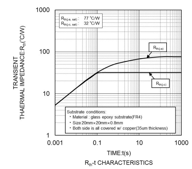
Datasheets either provide in tabular form or graph a parameter called Junction-to-Ambient. Junction-to-Ambient indicates the resistance provided by the diode package for the heat to escape out of the package. This is indicated by below graph in RB578VYM100FH datasheet.
Let us assume that the maximum ambient at which the system in which this diode is used in 85deg. As per above graph, for a given thermal resistance of 77C/W, at a power dissipation of 0.595W as we calculated above, for a maximum operating temperature of 85deg, junction temperature can raise up to
= 85 + (77*0.595) = 130.815deg
The junction temperature as per below specification from RB578VYM100FH is as below:
As the maximum Junction temperature the component can withstand is 150deg, from the above calculation with a power of 0.595W, it is safe to use the diode.


0 Comments